Differential Gaging: 2 Big Benefits for In-Process Part Control
Differential gaging offers benefits like reducing operator influence and enabling quick in-process checks.

Share


Differential gaging usually refers to the process of using two sensing devices and combining the results into one measurement. The measured dimension is the change in the position of the two sensing components.
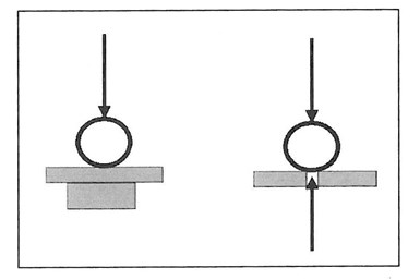
Figure 1: Fixed, single-gage setup vs. differential gage setup. Images courtesy of George Schuetz.
I’ve noted previously that differential gaging has some advantages over comparative measurements using a single, sensing head against a fixed, reference surface. One such advantage is the ability to measure size without regard to position (see Fig. 1). When the two gage heads are in line and in an opposed position, the sensed dimension will be the change in the separation of the two gage tips: in this case, the size of the part.


When measuring in this manner, the staging of the part does not become part of the measurement loop. The platen in a differential system simply places the part between transducers. With a single-head system, the platen is part of the measurement loop, and therefore flatness and configuration of the platen is critical.
There are a number of different measuring systems available that can provide differential gaging, including air and electronic gaging. Air gaging is probably the most common, since every two-jet air plug and air ring utilizes the differential gaging principle. Most air gages measure back-pressure that builds up in the system when the tooling is placed in close proximity to a workpiece. This results in higher air pressure, which the gage comparator converts into a dimensional value. Thus, as the plug fits into the part, it is the combination of both jets that represents the diameter of the part — without regard to where in the part the plug happens to be.
The same is true with electronic probes. In this case however, the probes are combined electronically to provide the differential measurement.
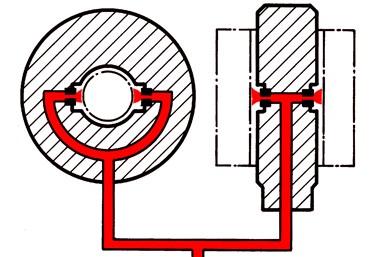
Clearance between mating parts (match gaging)
Moving a step further, we can now take this differential gaging (as seen with the air plug or a pair of electronic probes) and combine these circuits or channels differentially — a different differential. This differential gaging using either air or electronic probes can be deployed in a variety of applications, including measurement of angle on tapers and shafts without regard to the part dimensions. Also, concentricity of two shaft diameters, match gaging, squareness or checking parallelism of a workpiece and its support surface are all applications of this technique.
The distinctions between the two circuits for most of these differential applications is the result of the measurement that is being looked for. Take for example the match gage application. One differential circuit is measuring the OD while the other circuit is measuring the ID. If both diameters are zeroed on their masters, the system will conveniently show the clearance or interference between the two parts, basically comparing one diameter to another.
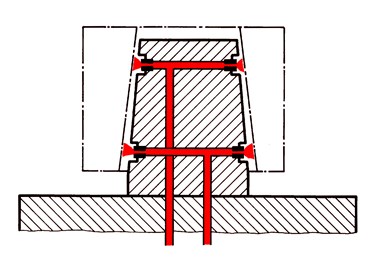
Measured angles for taper gaging
Now let’s look at the taper application. Taper is calculated by knowing three things: the two diameters and the distance between the two diameters. With a basic knowledge of right triangles and a display system to do the math, the results are the angle usually displayed in decimal angles or degrees. And if the angle has a tolerance applied to it this, the tolerance can be applied to this result.
But what if the amplifier being used is not that powerful, with no trig function but only length measuring capabilities? In this case, the angular deviation can be converted to a linear displacement. Using the pure linear differential displacement, where the angle deviation has been converted to a linear number, linear tolerances can be applied to the result and therefore check that angle using only the diameter deviation.
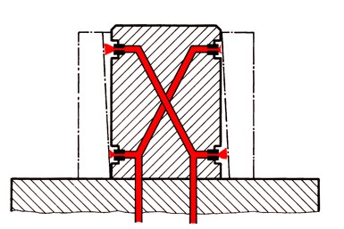
Squareness gaging setup
A squareness check is also differential measurement. By rotating a part around a squareness plug and monitoring the two circuits differentially, the total variation seen during the rotation is the out of squareness. With squareness checks and air tooling, there is an important consideration to remember.
Squareness is specified over the full length of the bore or cylinder being measured. As an example, the squareness tolerance might be 0.02 mm over the 30-mm bore length. With air gaging, because the jets must have full backpressure to function, they are not going to cover the full 30-mm bore length and must be brought inward away from the edges of the bore. Allowing for jet clearance, the circuit would enable the jets to be 24 mm apart. For this example, we are really measuring 24/30 mm, or 80% of the bore. Therefore, when classifying the part against the tolerance, one would have to use 80% of the tolerance for squareness. For this example, it would be 0.016 mm.
Differential gaging will help perform fast-form checks at the point of manufacture while reducing operator influence. This provides two big benefits for in-process part control.

Related Content

Using Digital Tap Testing to Measure Machining Dynamics
Tool-toolholder-spindle-machine combinations each have a unique vibration response. We can measure the response by tap testing, but we can also model it.
Read More
The Many Ways of Measuring Thickness
While it may seem to be a straightforward check, there are many approaches to measuring thickness that are determined by the requirements of the part.
Read More
Turning Fixed-Body Plug Gages Inside Out
Fixed-body mechanical plug gages provide fast, high-performance measurement for tight-tolerance holes.
Read More
How to Evaluate Measurement Uncertainty
Manufacturing and measurement are closely coupled. An important consideration for the use of measurement results is the associated measurement uncertainty. This article describes common metrology terms and provides an example uncertainty analysis.
Read MoreRead Next

Last Chance! 2025 Top Shops Benchmarking Survey Still Open Through April 30
Don’t miss out! 91ĘÓƵÍřŐľÎŰ's Top Shops Benchmarking Survey is still open — but not for long. This is your last chance to a receive free, customized benchmarking report that includes actionable feedback across several shopfloor and business metrics.
Read More
AMRs Are Moving Into Manufacturing: 4 Considerations for Implementation
AMRs can provide a flexible, easy-to-use automation platform so long as manufacturers choose a suitable task and prepare their facilities.
Read More
Machine Shop MBA
Making Chips and 91ĘÓƵÍřŐľÎŰ are teaming up for a new podcast series called Machine Shop MBA—designed to help manufacturers measure their success against the industry’s best. Through the lens of the Top Shops benchmarking program, the series explores the KPIs that set high-performing shops apart, from machine utilization and first-pass yield to employee engagement and revenue per employee.
Read More